How to Draw a Free Body Diagram in 6 Steps
The same six steps work on every problem, from a block on a table to a loaded bridge truss. Follow them in order and you will not miss a force.
Weight, then whatever each contact you removed supplies, then the applied loads. That is the whole checklist.
1 — Isolate the body
Decide what you are analysing and cut it away from everything touching it. Draw it as a simple shape: a box for a block, a line for a beam, a dot for a particle. Do not draw the ramp, the rope or the wall — each is about to become a force.
Objects that move together, like stacked blocks, can be treated as one body. Isolate them separately only when you need the contact force between them.
2 — Add the weight
One arrow, labelled W or mg, straight down from the centre of gravity. In introductory problems it is the only force that acts without touching.
3 — Turn each contact into a force
Walk the boundary of the body. Everywhere something was touching it, draw what that contact provides:
- Surface → normal force N, perpendicular to it, plus friction f along it if the surface is rough.
- Rope or cable → tension T, pulling away from the body along the rope. A rope can only pull.
- Spring → force along the spring axis, pushing if compressed and pulling if stretched.
- Support → a roller gives one reaction, a pin gives two, a fixed support gives two plus a moment.
4 — Add the applied loads
Whatever the problem states: pushes, pulls, distributed loads, applied moments. Put each at the point where it acts, with its magnitude and angle.
5 — Choose the axes
Draw a small x–y pair beside the diagram. On an incline, tilt it so x runs along the slope. That splits the weight into mg sin θ and mg cos θ and leaves N, f and any rope along the slope on an axis, which is most of the algebra done before you have written anything.
6 — Check before you solve
- Every arrow starts on the body, and every arrow is labelled.
- Count: weight, plus what each contact supplies (two for a rough surface or a pin, two plus a moment for a fixed support), plus the applied loads. An arrow that traces to none of these is one you invented.
- No “force of motion” and no centrifugal force. Motion is what forces cause, not a force.
- In equilibrium, could these arrows plausibly cancel? If they all point the same way, one is missing.
Worked example: block on a rough incline
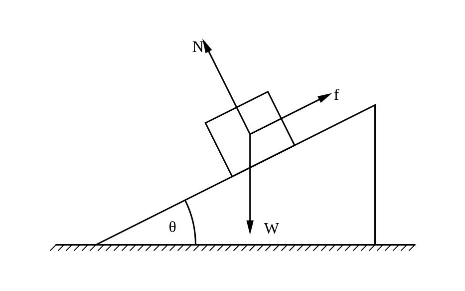
- Isolate — a tilted box. The ramp in the figure is only there to mark θ; leave it off your own diagram.
- Weight mg straight down.
- One contact, the slope: normal N perpendicular to it, friction f along it, pointing up-slope because the block tends to slide down.
- No applied loads in this problem.
- Axes tilted along the slope.
- Check: three arrows — weight, plus N and f from the one rough contact. Correct.
The equations drop straight out: N = mg cos θ perpendicular to the slope, and f = mg sin θ along it while the block stays put.
FAQ
How many forces should my FBD have?
Weight, plus one per contact — two if that contact is rough, since it gives both a normal force and friction (a pin also gives two, a fixed support two plus a moment) — plus any applied loads. An arrow you cannot trace to the weight, a contact or a stated load means you have invented a force.
Which way does friction point?
Against the sliding, or against the tendency to slide if nothing is moving yet. In statics you can simply guess: a negative answer means it points the other way.
Should acceleration appear on the diagram?
No. Acceleration is not a force. If it helps to note it, draw it beside the diagram, never on the body.